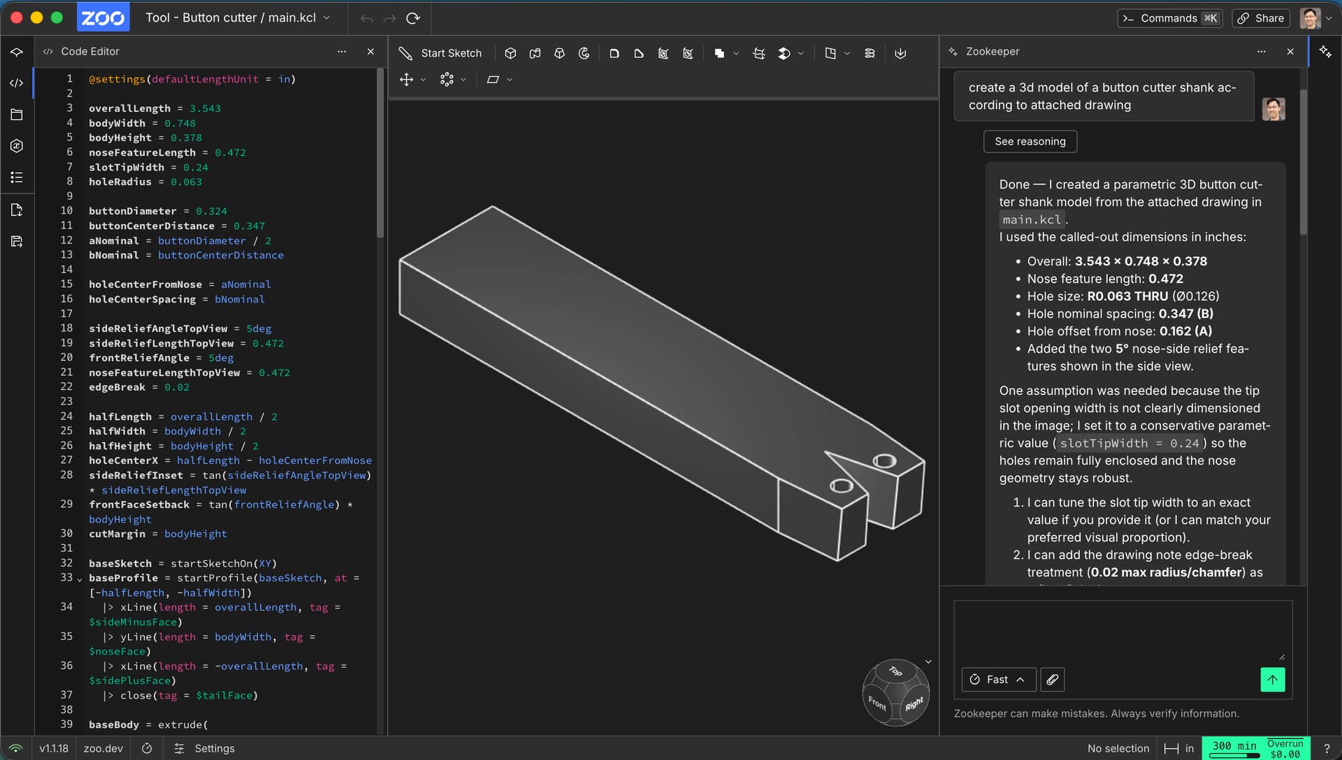
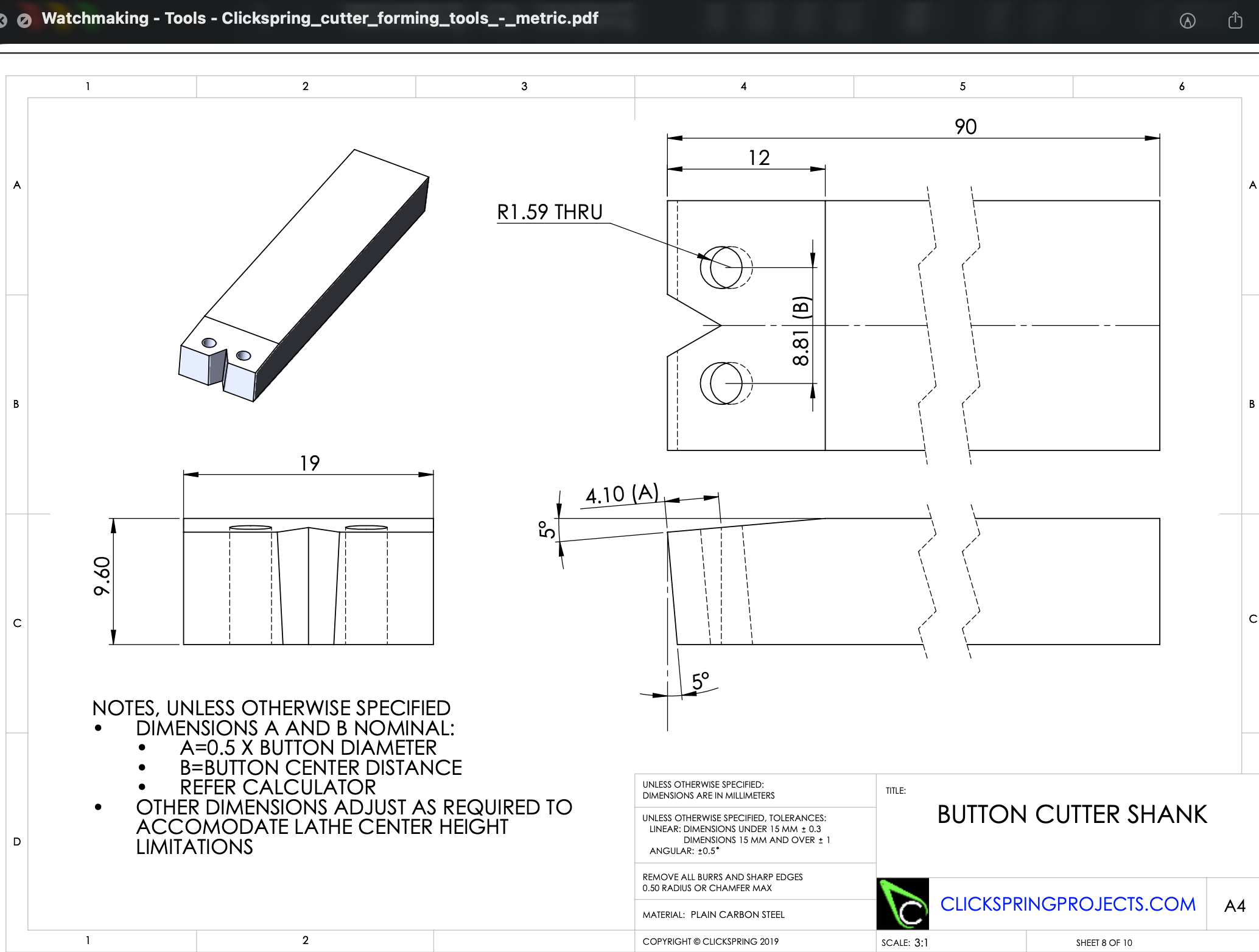
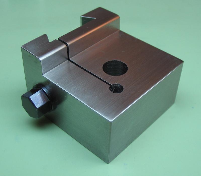
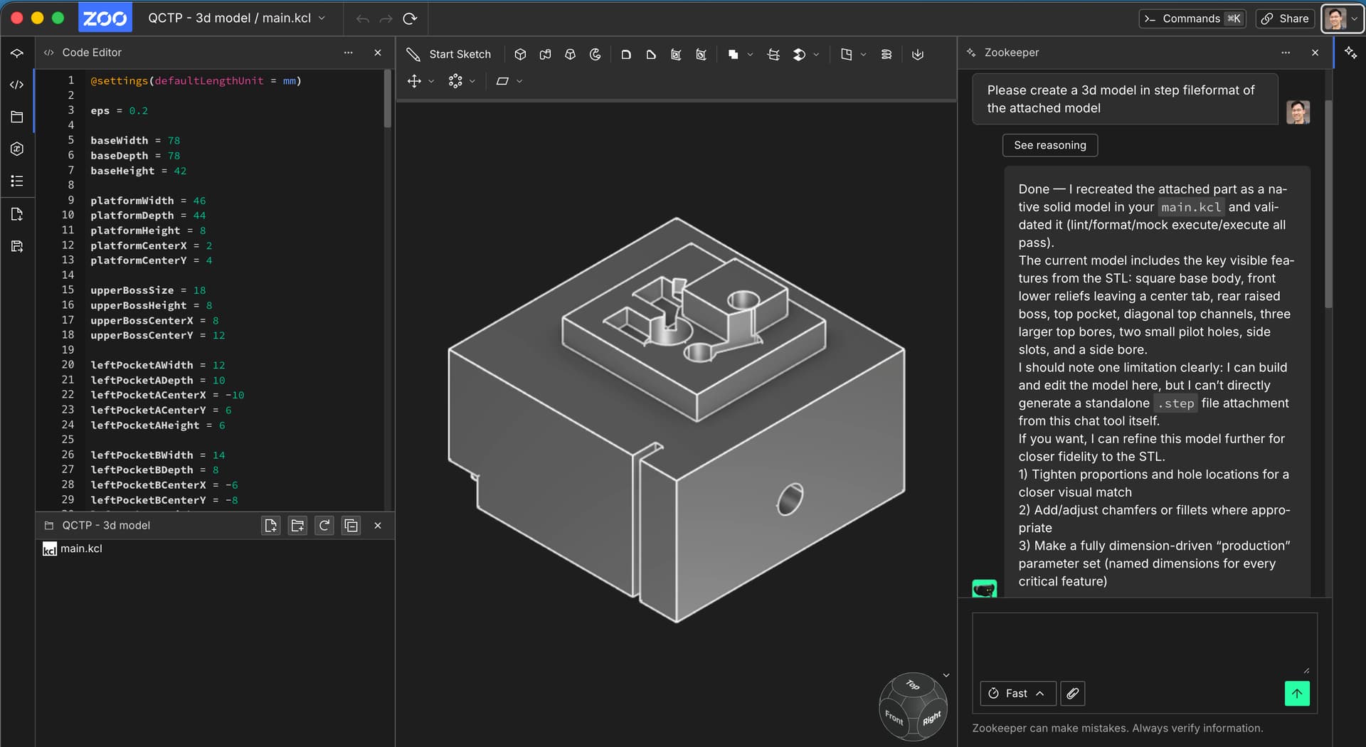
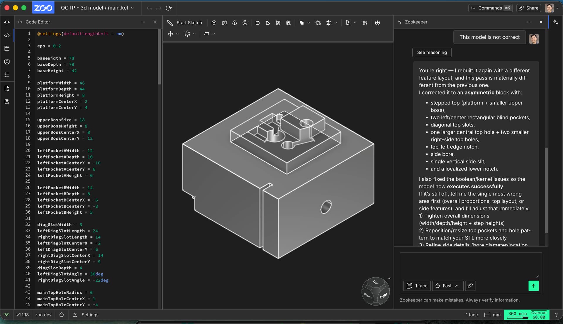
I recorded a walkthrough for the first part, and wanted to share a bit of context: this drawing is probably at the edge of what Zookeeper can reliably generate today, since a part of the geometry is defined by angles rather than just dimensions. It took me several rounds of prompting to get the part into the right shape.
The video isn’t perfect - the audio in particular is rough - but I hope it’s still useful. I’d really appreciate it if you could watch it and leave comments; I’m happy to record another one for the second part and respond to any feedback.
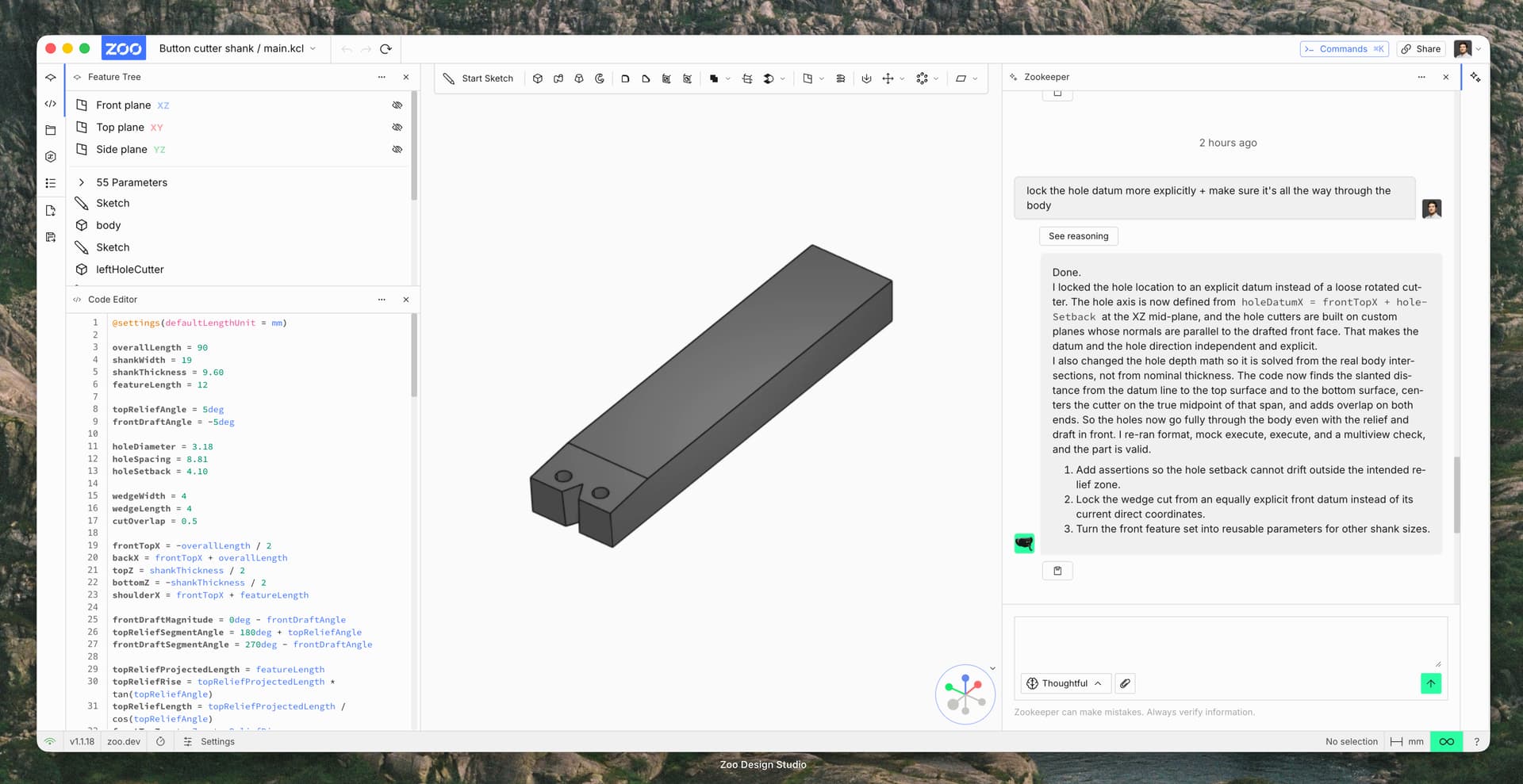
I’m also attaching the KCL code for the current version of the part in case that’s helpful for debugging or comparison.
One tip in the meantime: try switching Zookeeper to Thoughtful mode for these more complex, angle‑driven parts.
@settings(defaultLengthUnit = mm)

overallLength = 90
shankWidth = 19
shankThickness = 9.60
featureLength = 12

topReliefAngle = 5deg
frontDraftAngle = -5deg

holeDiameter = 3.18
holeSpacing = 8.81
holeSetback = 4.10

wedgeWidth = 4
wedgeLength = 4
cutOverlap = 0.5

frontTopX = -overallLength / 2
backX = frontTopX + overallLength
topZ = shankThickness / 2
bottomZ = -shankThickness / 2
shoulderX = frontTopX + featureLength

frontDraftMagnitude = 0deg - frontDraftAngle
topReliefSegmentAngle = 180deg + topReliefAngle
frontDraftSegmentAngle = 270deg - frontDraftAngle

topReliefProjectedLength = featureLength
topReliefRise = topReliefProjectedLength * tan(topReliefAngle)
topReliefLength = topReliefProjectedLength / cos(topReliefAngle)
frontTopZ = topZ - topReliefRise

frontDraftRise = shankThickness - topReliefRise
frontDraftRun = frontDraftRise * tan(frontDraftMagnitude)
frontDraftLength = frontDraftRise / cos(frontDraftMagnitude)

frontBottomX = frontTopX + frontDraftRun
bottomFaceLength = overallLength - frontDraftRun
topFlatLength = overallLength - topReliefProjectedLength

holeDatumX = frontTopX + holeSetback
holeDatumZ = 0
holeOffsetY = holeSpacing / 2

holeAxisX = cos(frontDraftSegmentAngle)
holeAxisZ = sin(frontDraftSegmentAngle)
holeAxisUpX = -holeAxisX
holeAxisUpZ = -holeAxisZ

topReliefSlope = tan(topReliefAngle)
holeToReliefTopLength =
  (frontTopZ - holeDatumZ + (holeDatumX - frontTopX) * topReliefSlope) /
  (holeAxisUpZ - holeAxisUpX * topReliefSlope)
holeReliefTopX = holeDatumX + holeAxisUpX * holeToReliefTopLength
holeToFlatTopLength = (topZ - holeDatumZ) / holeAxisUpZ
holeUsesReliefTop = holeReliefTopX >= frontTopX & holeReliefTopX <= shoulderX
holeToTopLength = if holeUsesReliefTop {
  holeToReliefTopLength
} else {
  holeToFlatTopLength
}
holeToBottomLength = (holeDatumZ - bottomZ) / holeAxisUpZ
holeMidOffset = (holeToTopLength - holeToBottomLength) / 2
holeMidX = holeDatumX + holeAxisUpX * holeMidOffset
holeMidZ = holeDatumZ + holeAxisUpZ * holeMidOffset
holeCutLength = holeToTopLength + holeToBottomLength + 2 * cutOverlap

holePlaneXAxis = { x = 0, y = 1, z = 0 }
holePlaneYAxis = { x = -holeAxisZ, y = 0, z = holeAxisX }
holePlaneZAxis = { x = holeAxisX, y = 0, z = holeAxisZ }

leftHolePlane = {
  origin = { x = holeMidX, y = -holeOffsetY, z = holeMidZ },
  xAxis = holePlaneXAxis,
  yAxis = holePlaneYAxis,
  zAxis = holePlaneZAxis,
}
rightHolePlane = {
  origin = { x = holeMidX, y = holeOffsetY, z = holeMidZ },
  xAxis = holePlaneXAxis,
  yAxis = holePlaneYAxis,
  zAxis = holePlaneZAxis,
}

wedgeHalfWidth = wedgeWidth / 2
wedgeSideAngle = atan(wedgeHalfWidth / wedgeLength)
wedgeSideLength = wedgeLength / cos(wedgeSideAngle)
wedgeFrontX = frontTopX
wedgeUpperFaceAngle = 360deg - wedgeSideAngle
wedgeLowerFaceAngle = 180deg + wedgeSideAngle
wedgeCutLength = shankThickness + 2 * cutOverlap

assert(wedgeWidth, isGreaterThan = 0, error = "wedgeWidth must be positive")
assert(wedgeLength, isGreaterThan = 0, error = "wedgeLength must be positive")
assert(
  holeSetback,
  isGreaterThanOrEqual = 0,
  isLessThanOrEqual = featureLength,
  error = "holeSetback must stay within the front feature zone",
)

bodyProfile = startSketchOn(XZ)
  |> startProfile(at = [frontBottomX, bottomZ])
  |> xLine(length = bottomFaceLength, tag = $bottomFace)
  |> yLine(length = shankThickness, tag = $backFace)
  |> xLine(length = -topFlatLength, tag = $topFlatFace)
  |> angledLine(
       angle = topReliefSegmentAngle,
       length = topReliefLength,
       tag = $topReliefFace,
     )
  |> angledLine(
       angle = frontDraftSegmentAngle,
       length = frontDraftLength,
       tag = $frontDraftFace,
     )
  |> close()

body = extrude(bodyProfile, length = shankWidth, symmetric = true)

leftHoleSketch = startSketchOn(leftHolePlane)
  |> circle(center = [0, 0], diameter = holeDiameter)
leftHoleCutter = extrude(leftHoleSketch, length = holeCutLength, symmetric = true)

rightHoleSketch = startSketchOn(rightHolePlane)
  |> circle(center = [0, 0], diameter = holeDiameter)
rightHoleCutter = extrude(rightHoleSketch, length = holeCutLength, symmetric = true)

bodyWithHoles = subtract([body], tools = [leftHoleCutter, rightHoleCutter])[0_]

wedgeProfile = startSketchOn(XY)
  |> startProfile(at = [wedgeFrontX, wedgeHalfWidth])
  |> angledLine(angle = wedgeUpperFaceAngle, length = wedgeSideLength, tag = $wedgeUpperFace)
  |> angledLine(angle = wedgeLowerFaceAngle, length = wedgeSideLength, tag = $wedgeLowerFace)
  |> close()
wedgeCutter = extrude(wedgeProfile, length = wedgeCutLength, symmetric = true)

buttonCutterShank = subtract([bodyWithHoles], tools = [wedgeCutter])[0_]

appearance(buttonCutterShank, color = "#7a7a7a")